 |
||||||
BOILERS
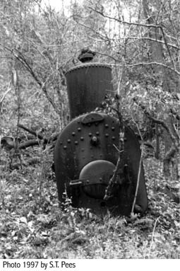 |
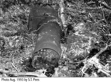
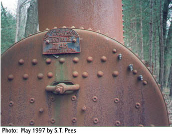
They are big and unmistakable. They "own" their piece of the lease. This is a head on view of a locomotive type boiler abandoned in the oilfield. The oval door opens to the fire box. This boiler was made by the Boiler Department of Oil Well Supply Co. in Oswego, New York. |
The locomotive type boiler was common among the standard oil country boilers. It resembled that of an early train engine and, in fact, was based on the famous Stephenson design in his 1833 locomotive from which other components of oil field steam engines were also derived including the link valve gear.
|
||
|
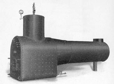

The main components of these large locomotive boilers bore the following names and dimensions (approximate average for 25 HP boilers of the 1880's):
|
overall length |
14 ft |
|
|
barrel (dia.) |
40" |
|
|
fire box (length) |
48-51" |
|
|
grate |
7 sq. ft. |
|
|
fire door |
16" dia. |
|
|
dome (height) |
36" |
|
|
tubes (dia.) |
3" |
|
|
tubes (length) |
96" |
|
|
tubes (number) |
43-48 |
|
|
stack |
25 ft. |
The boiler specified above would weigh about 6,800-7,600 lbs. It would come with fittings such as guy rods, hand hole plates, bonnet, gauges, siphon, cocks, check valve, globe valve and pop safety valve. Prior to leaving the factory, it would have been tested at high pressures to check for steam leaks. The maximum steam working pressure would be about 100 psi.
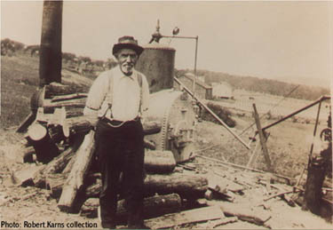 |
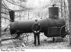
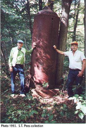
This locomotive-type was located in a field on the east side of Carter Road in Cherrytree Township, Venango County, PA. The site was fairly high on the west flank of the Benninghoff Run system, part of Oil Creek Valley. It probably is a "Sunday" picture since the man doesn't seem to be in appropriate work clothes and not much is going on. The boiler closely resembles the ACME make. It is putting out some steam (see connection at right). One guess is that the boiler operated a drilling rig engine. The alternative would be a pump, but the photo doesn't give much evidence of either. The farm buildings and houses in the background would be on the Bryner parcel. This area is deeply forested today. Photo date probably late 1800's. |
The companion type layout would consist of a locomotive boiler at a distance, then the steam engine in a roofed space, followed by the belt way to the walking beam unit in the standard derrick. This was considered the safest arrangement and was commonly set up that way for drilling from the mid 1870's into the 1900's. The mounted combination boiler and engine (like the Wood & Mann make) declined in favor of the locomotive boiler and separate engine in the 1870's -80's.
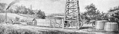 |
This layout was considered ideal in 1892 (and before). The locomotive type boiler was considerably removed from the rig so that sparks wouldn't fly to the other operations and the oil tanks. The latter were placed as far away from the boiler and steam engine as possible. This well is being pumped (singly) which is a rather elaborate use for the steam set-up. |
The locomotive type boiler carried the same outward look into the 1920's and perhaps later. There were internal improvements. Beginning with Spindletop in 1901, the boilers were being used for the newly applied rotary drilling system that reached greater depths. This brought about more improvements such as super heater tubes in the upper flues, stronger plates, and other benefits resulting in higher horse power (up to 125 HP). These improved boilers were on the market in the 1930's, maybe before, but were not much in evidence in the Appalachian oil region.
|
||
|
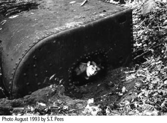
The number and length of tubes seem to be an identifier of the power and efficiency of the locomotive boiler. They can usually be seen and measured even in old, damaged, abandoned boilers. In general, the greater number of tubes and greater lengths of the tubes imply greater boiler horse power. Locomotive type boiler tubes (also called flues) as seen by the author in the field and in catalogs ranged from 19 to 80 in number. A 25 HP locomotive type boiler in the late 1800's and early 1900's usually had 48 tubes having a length of 96 inches (8 feet). A 20 HP boiler as made by Oil Well Supply Co. had 36 tubes, 8 feet long.
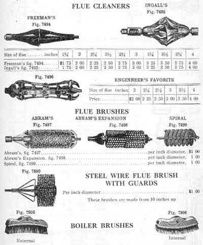
Hard water caused a lot of problems in boilers, but the operators had to take whatever water the supply offered. They usually used stream or spring water. Minerals would precipitate and coat the flues (tubes) gradually restricting the steam flow. All boiler companies offered cleaners, brushes and scrapers which bore names (some from patents) like Freeman's Flue Scraper, Ingall's, Abram's expansion brushes and the Engineer's Favorite. Some were rather complicated in design while others were simple wire brushes.
 |
The boiler tubes required periodic cleaning so that scale would not build up. |
The locomotive type boiler was at work in the oilfields since the early days of oil all over the world. The manufacturers built special boilers to meet the requirements and regulations of the Canadian Provinces, Burma and of the Dutch East Indies (Indonesia). Specially built California type boilers were rugged and would operate an engine from one site to drill a considerable number of wells spaced around it.
Beginning about 1910 the American Society of Mechanical Engineers (A.S.M.E.) developed a code of boiler specifications which was followed by the manufacturers. Then in 1926 the American Petroleum Institute (A.P.I.) issued detailed standards for boilers but still worked within the A.S.M.E. code.
|
||
|
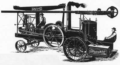
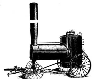
Radical departures from the portable horizontal locomotive type boiler were to be seen in a number of styles that were used in the oilfields, even from the 1870's, but more noticeable later in that century and in the 1900's. Among these were the vertical boiler, T-shaped, semipermanent (California), tubular boiler and others. According to one manufacturer (STAR Drilling Machine Co., Akron, Ohio) the T-shaped boiler and steam engine on their traction drilling machine allowed it to be driven 3 MPH on level roads and 1 1/2 MPH in hilly terrain (it had cleats on the wheel rims).
|
||
|
||
|
Besides indicating the oil production rate, well completion reports in the Pennsylvania oilfields in the 1860's (and on) gave the amount of natural gas produced by estimating how many boilers it would fire. The latter was usually expressed as "gas sufficient to fire 3 boilers" (or whatever number). Fuel used in the boilers varied due to circumstance. It could be wood, coal, natural gas from the lease and, later in time, fuel oil.
A few locomotive type boilers are still to be found where abandoned long ago in the oilfields, but they are very rare. They are great sights and have a commanding presence due to their bulk. The author together with Robert Karns found an old oilfield boiler caught in a sand bar in a deep ravine where it had been washed by floods. Others were removed from the well sites and just dumped wherever, presumably out of sight or out of the way at the time. Most went to the scrap pile. Anyway it is doubtful if the tools still exist to work on these discarded giants. The steam engines and boilers were replaced in the oilfields by internal combustion engines.
After the cable tool days were largely over in most oil basins, steam became the power plant for rotary drilling and hung on for years in the 1900's. The author remembers the rows of steam boilers set up at the drilling rigs in 1954 in Eastern Venezuela.
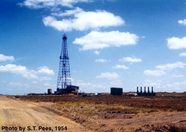 |
A 15,000 foot Mata field well being drilled by Texas Petroleum Company in the llanos of Anzoategui, Eastern Venezuela, 1954. Note row of boilers. This is a rotary well. |
![]()
![]()
| © 2004, Samuel T. Pees all rights reserved |
|